AIM-9/2 Sidewinder!
1/2 SemiScale H Powered AIM-9 Sidewinder High
Powered Rocket Project
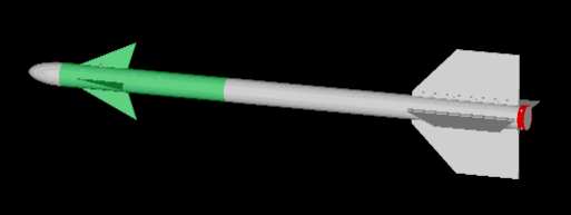 The overall
design of the rocket is shown in the picture at the right. The body design
follows the basic lines and scale dimensions of the Sidewinder missile using
a sectioned tube fuselage, a conical nose cone, and front and rear fins.
The overall
design of the rocket is shown in the picture at the right. The body design
follows the basic lines and scale dimensions of the Sidewinder missile using
a sectioned tube fuselage, a conical nose cone, and front and rear fins.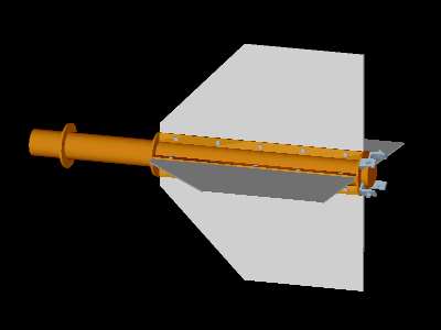 The motor section
is based around a 38mm motor tube which houses the motor, either reloadable
or single use. The motor tube is centered inside the body tube through the
use of 3 centering rings: one in the front which rests against the
forward bulkhead and one on each end of the rear fin section. Also attached
to the motor tube are 8 rear fin mounting flanges - 2 flanges for each
fin. The rear fins are attached to the fin mounting flanges by means of
bolts allowing the fins to be replaced. The motor section assembly is completed
by the use of 4 L-brackets attached to the back centering ring. These are
fastened to the body tube by means of 4 bolts that go through the L-brackets
and the fuselage tube to prevent rearward travel of the motor section during
ejection charge firing.
The motor section
is based around a 38mm motor tube which houses the motor, either reloadable
or single use. The motor tube is centered inside the body tube through the
use of 3 centering rings: one in the front which rests against the
forward bulkhead and one on each end of the rear fin section. Also attached
to the motor tube are 8 rear fin mounting flanges - 2 flanges for each
fin. The rear fins are attached to the fin mounting flanges by means of
bolts allowing the fins to be replaced. The motor section assembly is completed
by the use of 4 L-brackets attached to the back centering ring. These are
fastened to the body tube by means of 4 bolts that go through the L-brackets
and the fuselage tube to prevent rearward travel of the motor section during
ejection charge firing.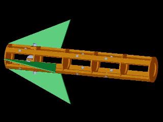 The payload
section's primary function is to support payloads and the front fin assembly.
It is consists of a frame formed by a series of bulkheads connected by
a stringers. The removable front fins are mounted on axles that are supported
by bearings on one of the bulkheads. The payload frame is attached to the
rear section of the payload portion of the fuselage by four bolts through
the fuselage tube and payload section frame. It is secured from rearward
movement by a rear payload bulkhead. The frame is attached to the nose
section (fuselage tube forward of the front fin attachment and nose cone)
by two bolts through the fuselage tube and payload section frame. Additional
cross braces and mounting brackets are attached to the payload frame as
needed by the specific payload.
The payload
section's primary function is to support payloads and the front fin assembly.
It is consists of a frame formed by a series of bulkheads connected by
a stringers. The removable front fins are mounted on axles that are supported
by bearings on one of the bulkheads. The payload frame is attached to the
rear section of the payload portion of the fuselage by four bolts through
the fuselage tube and payload section frame. It is secured from rearward
movement by a rear payload bulkhead. The frame is attached to the nose
section (fuselage tube forward of the front fin attachment and nose cone)
by two bolts through the fuselage tube and payload section frame. Additional
cross braces and mounting brackets are attached to the payload frame as
needed by the specific payload.